Usb Stick Floppy Emulator
Posted By admin On 12.10.19
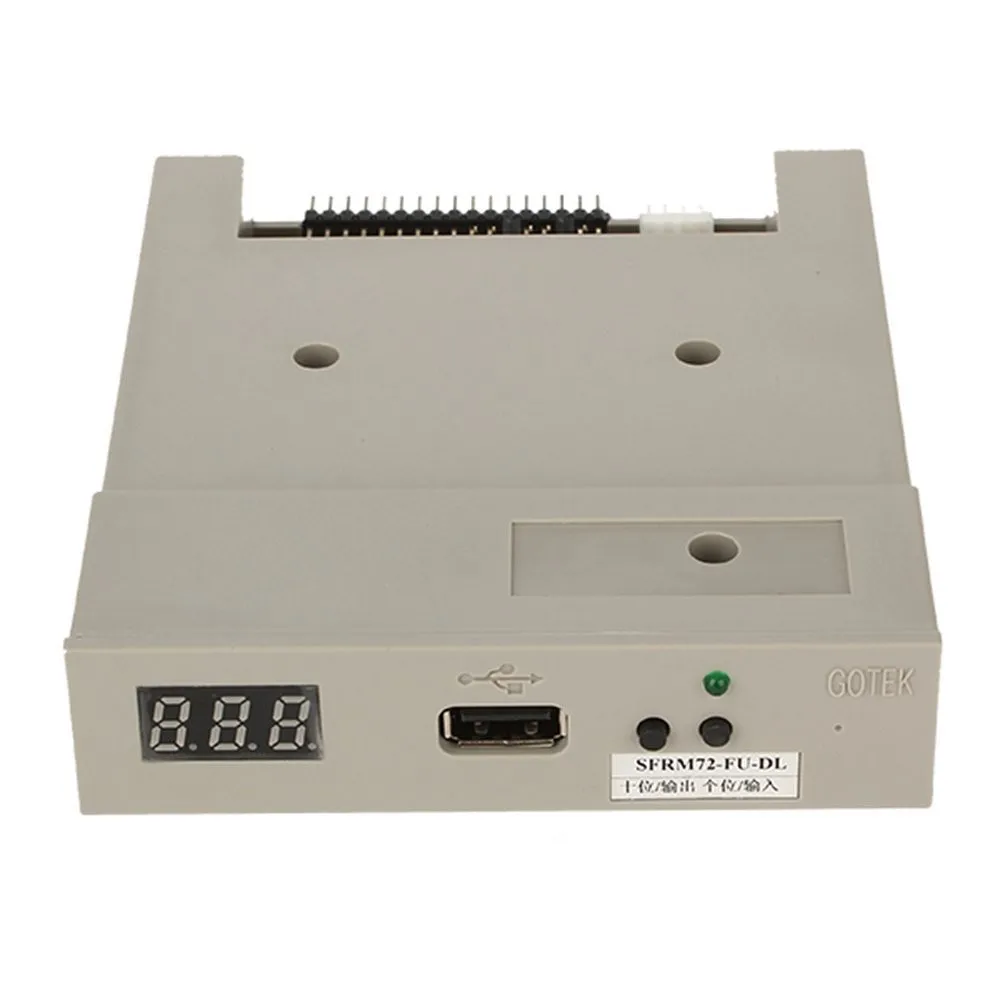
Use normal usb flash drive as the medium for transfer design. 34pin floppy driver interface, 5V DC power supply, easy to install. Capacity: 1.44MB 2HD Cylinders: 80 Tracks: 160 Sectors/Track: 18 Bytes/Sector: 512 Data transfer rate: 500 kbps Encoding method: MFM. 1000pcs partitions in usb flash drive can be used. Built -in self -format function. I recently purchased the beige gotek USB floppy emulator, with the LCD readout and two button control on the front panel. I have a straight through floppy ribbon cable, a 3.5' power cable, and a usb stick. I've installed the unit in my PEB using the original TI disk controller. The ribbon cable is connected to the interior port.

No more floppydisk and floppy drive!!!Simply install floppy to usbManual - Floppy to USBUniversal emulator 1.2MB ( 34 Pin Interface )Note:Before we start using the floppy to usb emulator,few noticeable things should be kept in mind. The front of the floppydisk to usbconverter has two switches. These switches act differently in twoscenarios ( one scenario is that when USB drive in inserted in the usbport of floppy disk to usb and the other is without inserting ). Whenthe usb flash is not being used in usb as floppy drive emulator the switches are used tochoose the folders present in USB disk.
By pressing the left button offloppy drive to usb the counter will advance by 10 ( that is 10, 20,30. ), and by pressing the right button of floppy disk drive to usbthe counter will advance by 1's ( that is 1,2,3. So if user wantsto select folder 26 to perform action, userwill have to press left button two times and right switch 6 times. Oncethe flash disk is plugged in the floppy disc to usb conversion unit, thefunctions of the two button change. Now the keys will perform as Data-out and Data-in.Pressing the right switch on the floppy to usb converter will replicatethe data in the selected folder from flash drive into the memory offloppy disk to usb converter.

As we pressthe right button of usb as floppy drive emulator, the8-Segment displays D0 ( signaling that the data from folder starting withname 025 in usb drive is being copied in the 2 mb internal memoryof floppy drive to usb emulator). User can also name the block / folderwith anythingstarting with 025., where `.’ is any other digit oralphabet.
Usb Stick Stm32 Hxc Floppy Emulator
SD HxC Floppy Emulator Mechanical drawing (Rev B/C):Firmware:Please go to theHost control/File selector tool (Atari ST, Amstrad CPC, Amiga):With the HxC File selector the host computer can access directly to the SDCard to select files images and change the SDCard HxC Floppy Emulator settings.The LCD screen and the buttons are becoming optional / useless. You can even remove the LCD screen to put the SD HxC Floppy Emulator inside the Amiga/Atari/CPC computer without case modification.Atari ST, Amstrad CPC and Amiga versions of this tool are currently available.Videos-demo of the HxC File Selector:Note: Please go to theUSB HxC Floppy Emulator USB HxC Floppy Emulator hardware main features- Read only Floppy emulator (SD,DD,HD & ED mode)( No Write Support! )- USB 1.1 device interface (based on the.).- MFM, FM and GCR compatible (can handle custom encoding).- Bitrate between 63Kbits/s and 1MBits/s.(250 differents bitrates by step of 62.5ns).- Variable bitrate, flakey bits and long tracks, custom tracks support (emulation of copy protected floppies).- Can emulate floppies up to 128 tracks.- 'jumper free' design: Device configuration done by software.- Flexible floppy interface: Shugart, IBM PC and Amiga compatible.To see the list of computer tested with it, please go to this. All necessary informations to build your own USB HxC Floppy Emulator are available here.The main part of the USB HxC Floppy Emulator is a MAX EPM7128S CPLD from Altera with 128 Macrocell.This chip is connected to a 32KB SRAM memory buffer and a FT245 from FTDI for the USB communication.Warning: Do not disconnect the floppy ribbon while the USB is connected!
Usb Floppy Disk Drive Emulator
This may damage the emulator and your equipements.Always disconnect the USB cable before connect/disconnect the floppy ribbon.USB HxC Floppy Emulator's schematicUSB HxC Floppy Emulator CPLD. The to use to program the CPLD is.To program this chip you can use Quartus II and an Altera compatible JTAG probe ( for example).The programmer software can be.Note: The EPM7128S CPLD can also be remplaced with the Atmel ATF1508AS.Once programmed the CPLD got this pinout -There are four LEDs on the board:D1: Power LED.D2: Select LED: Is on when the target computer acccess the floppy disk.D3: Step LED: Is on when the target computer is stepping/changing track.D4: Link LED: This is the USB link status: Is on when dialoging the host PC.The VHDL sources are available here. How to build the USB HxC Floppy Emulator?There are two differents USB HxC Floppy Emulator PCBs:- An 'homebrew' version (Rev B). This is a one layer 'Do It Yourself' PCB.- A 'Production' version (Rev C). This is a two layers PCB. DocumentationsDocumentations (developer)OtherDownload: USB Stick STM32 HxC Floppy Emulator (aka HxC Firmware for Gotek!)The following elements allow you to program the low cost Gotek USB Floppy Emulator with the HxC bootloader & Firmwares.To purchase the firmware: USB HxC Floppy Emulators firmware for Gotek(HFE + HFEv3 + ADF + ST + IMG + (E)DSK file and many others format support)Please have a look toSoftwares and tools(please have a look to ) Softwares and Libraries sources can be found on SourceForge and GitHub.